.png)

Ask a fabricator what actually slows a job down, and connection ambiguity comes up almost every time. It's rarely the big stuff; missing dimensions get flagged early. It's smaller: a bolt pattern that doesn't match the beam, a weld symbol that contradicts the spec sheet, a piece mark that doesn't line up with how the crew is sequencing steel. None of this shows up in the office. It shows up on-site, with a crew standing around a beam that won't sit where it's supposed to.
Shop drawings exist to head this off. They take an engineer's structural design and turn it into something a shop can cut, drill, and weld without reinterpreting anyone's intent. Done well, nobody has to guess. Rushed, and every guess turns into a delay, a change order, or worse.
This piece covers what a complete, buildable shop drawing package actually needs, where detailing teams tend to slip, and what separates a set that works from one that generates RFIs for a month.
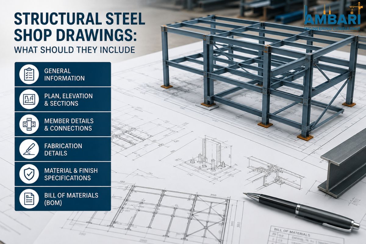
A shop drawing is a fabrication-level document built off the structural engineering drawings. It shows individual members, beams, columns, braces, plates with exact dimensions, connection details, material grades, and piece marks, so a fabrication shop can produce each piece without having to guess at what the engineer meant.
Moreover, the distinction from design drawings comes down to purpose. Design drawings communicate structural intent and load path. Shop drawings communicate exactly how to cut and assemble the steel. The structural engineer signs off on the design, a detailer produces the shop drawing from it, and the engineer reviews that drawing for conformance, not to re-engineer it.
This is where firms offering steel fabrication drawings services in USA tend to earn their fee. A detailer who knows AISC standards and has actually stood on a shop floor catches conflicts before they reach the cutting table, not after.
Owners, and honestly some project managers too, treat shop drawings as a formality wedged between design approval and the start of fabrication. In practice, they're closer to a second round of engineering coordination.
A poorly detailed set has a way of cascading:
A detailer who's spent real time on a shop floor writes different drawings than one who hasn't set foot on one. They know which connections eat up more welding time, which bolt patterns run into clearance trouble, and where tolerances genuinely matter versus where they got copied from an old template and nobody questioned it.
A complete package generally covers the following, though the exact breakdown shifts with project scope and specification.
| Element | Purpose |
|---|---|
| General notes and specifications | Material grades, applicable codes (AISC, AWS), coating requirements |
| Piece marks | Unique identifiers for every fabricated member, matching the erection sequence |
| Member dimensions | Length, cross-section, camber, hole locations |
| Connection details | Bolt sizes, weld symbols, plate thicknesses, edge distances |
| Bill of materials | Quantities, sizes, and grades of steel required |
| Anchor bolt layouts | Coordinates and elevations for foundation connections |
| Cambering and fabrication tolerances | Allowable deviation limits per AISC Code of Standard Practice |
The checklist gets you partway there. What actually separates a usable set from an average one comes down to a few things.
Furthermore, clarity matters more than completeness. A drawing can hit every required item on the list and still be a pain to build from if the layout is cluttered or the piece marks don't follow any logic. Detailers who've worked shop floors tend to organize drawings the way a fitter actually reads them, top to bottom, connection by connection, not the way a template happens to lay things out.
Piece marks also need to stay consistent with whatever numbering gets used later for steel erection drawings services in USA projects. A mismatch here is one of the more common reasons field work stalls.
Additionally, every dimension, every connection, should trace back to a specific structural drawing or calculation. If a reviewer can't find where a detail originated, that's worth flagging before anything gets cut.
If one section of a shop drawing deserves extra scrutiny, it's the connections. Overall beam lengths and column heights are usually straightforward; they come straight off the structural drawings. Connections are where someone has to interpret intent, and that's where things go sideways.
A few things worth watching for:
Firms working in structural steel detailing services USA generally push connection details through two checks, not one: does it meet code, and can a fitter actually put this together with the tools sitting on the shop floor?
These two get mixed up often enough that it's worth spelling out plainly.
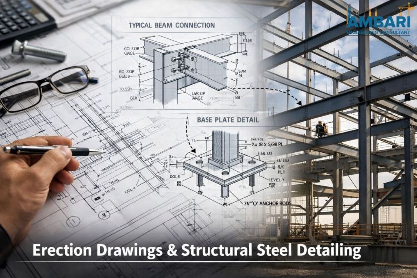
Shop drawings tell the fabrication shop how to build each piece. Erection drawings tell the field crew how to put those pieces together on-site, in what order, and where each one lands relative to the building's grid lines and elevations.
A shop drawing might show one beam in isolation, every hole and weld dimensioned out. An erection drawing shows that same beam in context, positioned against columns, connected to whatever's next to it, sitting in its place in the lifting and setting sequence.
Both documents have to agree on piece marks, material specs, and connection types. When a project brings in steel erection drawings services in the USA as a separate team from the shop drawing crew, coordination between the two is optional. Any renumbering, any late design change, has to land in both sets, or the field crew ends up working off information that's already out of date.
Once a detailer finishes the first pass, it usually moves through a cycle like this:
Skipping or rushing any of these is usually where the expensive mistakes come from. A detailer under deadline pressure might send out a set with a minor connection inconsistency, betting it gets caught in review. Sometimes it doesn't, and the shop just builds to the error.
A few patterns turn up again and again, regardless of project size or region:
Therefore, most of these aren't gaps in knowledge. They're process failures, usually the result of a compressed timeline or a detailing team that isn't talking to the fabrication shop enough.
Detailing has largely shifted from manual 2D drafting to 3D modeling environments that generate shop and erection drawings off a single coordinated model. That shift has cut down, though not eliminated, the kind of dimensional conflicts that used to slide past manual cross-checking.
The upside of a model-based approach is that a change to one member flags conflicts elsewhere automatically. The catch is that the model only knows what the person building it knows. Clash detection catches geometric conflicts. It won't catch a detailer who misread a spec or borrowed a connection type from a similar project that turned out not to be similar enough.
When you're evaluating a provider for steel fabrication drawings services in USA, a handful of practical questions tend to tell you more than a portfolio walkthrough:
Moreover, familiarity with AISC's Code of Standard Practice and regional fabrication norms tells you more than technical proficiency on its own. The drawings still need to reflect how steel actually gets built in the specific shop assigned to the job.
A structural steel shop drawing is a working document, not paperwork sitting between design and fabrication. Get the connection details right, keep piece marking consistent, and maintain a clear line back to the structural design, and a project saves weeks it would otherwise lose to rework. Rush it, and those same gaps surface as delays on-site, usually at the point in the schedule where nobody wants them.
If you're lining up detailing support from shop fabrication drawing services in USA for an upcoming project, Ambari Consultant works directly with fabrication and erection teams to produce shop drawings that hold up from the drafting table through to the field.
Structural drawings carry the engineer's design intent and load path. Shop drawings turn that into fabrication-level detail, exact dimensions, connections, and piece marks a shop can build from directly.
Usually a detailer working for the fabricator. The Engineer of Record then checks the drawings against the original design.
At minimum: piece marks, member dimensions, connection details, material grades, a bill of materials, and fabrication tolerances that follow AISC standards.
Because someone has to interpret design intent into a specific bolt pattern, weld type, and clearance, and small misreads there change what the connection can actually hold.
No. Shop drawings guide how pieces get built; erection drawings guide how they get assembled on-site. Piece marks need to match across both.
Depends on how complex the project is, but most sets go through at least one round of markups before final sign-off, so build that into the schedule.
Whatever error is in that unapproved set gets built straight into the steel, and fixing it later usually means rework, re-fabrication, or field modification.
Yes, but it's expensive and slow. Revision tracking between the design team, the detailer, and the shop has to stay tight, or someone builds to an outdated drawing.
It sets the baseline tolerances, connection assumptions, and standard practices that shop drawings are expected to follow.
Ask how much they coordinate directly with fabrication shops. Detailers with real shop-floor experience tend to draw connections that are easier to build, not just easier to sketch.
.jpeg)