.png)

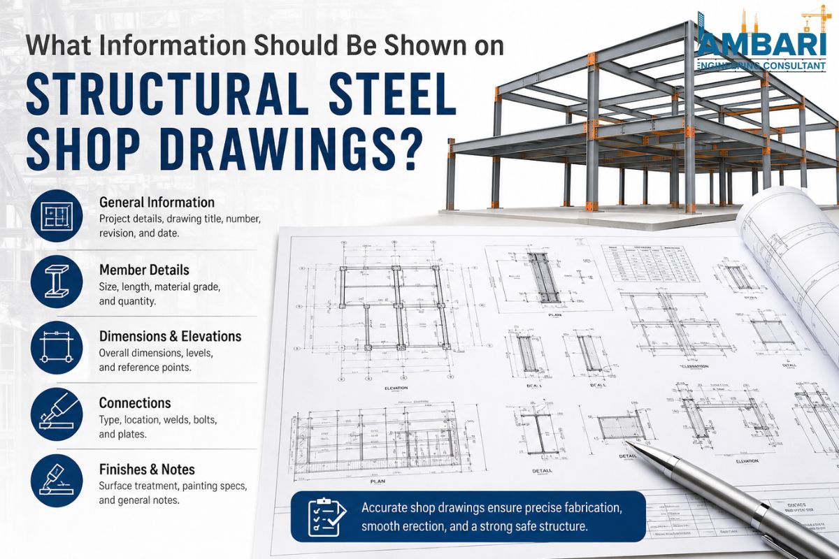
The shop drawings for structural steel must depict the sizes of the members, their respective piece marks, types of connection, marking of welds, bolt type, specifications of the material used, and requirements for surface finish and size tolerance. The detailing should be adequate for a fabricator to fabricate and weld the members without any ambiguity regarding what needs to be done.
The shop drawings must also cite the relevant codes, which usually relate to AISC 360 and AWS D1.1, and comply with the structural engineer's design specifications. A good steel fabrication detail service in the USA ensures that the drawings are created section-wise with cross-verification of the connections with engineering calculations. Not providing adequate details doesn't save time, but only shifts the problem further down the line, usually at a greater cost.
A shop drawing refers to the transfer of information from an engineering design to a fabricator's cutting apparatus. The structural engineer carries out calculations and makes a design. However, it will still be necessary to convert the information into step-by-step instructions in a way that allows for the shop to create something from it.
If this transfer is not done properly, the fabricator will be left with two choices: either to attempt to guess or to call in for assistance. Guessing will result in complications during implementation. Moreover, communicating with the engineer leads to delays. Unfortunately, both of these choices are expensive. It should be noted that in the case of a mid-scale commercial project, the absence of a connection detail can delay the entire installation of trusses, as it would require the engineer to be contacted for consultation.
Therefore, it is possible to conclude that quality projects cannot treat detailing as an additional stage of the project.
At minimum, a usable shop drawing needs:
Furthermore, miss the piece marks and the erection crew can't match steel to the field drawing. Miss the weld symbols and the welder is left interpreting intent. Structural steel detailing services USA generally build a checklist around exactly this list before a drawing goes to fabrication. It's rarely one big error that causes problems. It's usually one small omission, repeated across dozens of pieces.
This is where shop drawings earn their reputation as the hardest part of detailing to get right.
A connection detail has to show the bolt pattern, edge distances, gusset plate dimensions, and weld sizes together, not as separate notes but as one coordinated picture. Get the bolt spacing wrong by half an inch and the plate won't align on site. Specify the wrong weld size and you either under-strengthen the joint or waste filler metal on an oversized weld that wasn't needed.
However, moment connections need even more precision. Stiffener plates, continuity plates, and weld access holes all have to be dimensioned individually. Their positions often depend on the beam's exact depth and flange thickness, which varies slightly even within the same nominal size.
Firms offering Steel Connection Detailing Services in USA typically run these joints through a secondary check, separate from the general dimensioning pass. Connection errors are disproportionately expensive to fix once steel is already cut.
Beyond connections, a shop drawing carries the practical instructions a fabricator needs on the floor:
| Information Type | What It Specifies |
|---|---|
| Overall dimensions | Length, width, depth of each member |
| Hole locations | Diameter and position for bolts |
| Cope and notch details | Where beams need to be trimmed to fit |
| Cut lengths | Exact fabrication lengths, accounting for connections |
| Material certification notes | Mill test report requirements, if specified |
| Tolerances | Acceptable dimensional variance per AISC standards |
There is much more to tolerances than one may think. Even though AISC has breakpoints for the lengths and camber of construction members, slight differences in member length and camber can cause cumulative problems for the overall structure.
Shop drawings need to specify the desired tolerances. If that doesn't happen, the steel fabricators will tend to use the industry standard tolerances that may not be applicable in cases where tight tolerances are required, such as on curtain wall interfaces or precast joints.
These two document types get confused often enough that it's worth separating clearly.
Shop drawings are piece-level instructions, one drawing per beam, column, or plate, showing everything the fabricator needs to build that individual piece. Erection drawings are assembly-level instructions. They show where each piece goes on the structure, in what sequence, and how pieces connect in the field.
A fabricator works from shop drawings. An erection crew works from erection drawings. They reference the same piece marks, but they answer different questions: how do I build this, vs where does this go.
Confusing the two, or assuming one can substitute for the other, is a mistake that shows up more often than it should, especially on smaller projects trying to cut detailing costs.
Shop drawings in the US typically reference:
Furthermore, a drawing that doesn't align with these references can still look complete on paper and still fail inspection. Reviewers, particularly on projects requiring special inspection under IBC, check weld symbols against AWS D1.1 conventions specifically. Non-standard notation gets flagged even when the intended weld is correct.
A few patterns show up repeatedly across projects, regardless of size:
None of these are complicated fixes. They're just easy to miss when a drawing gets rushed.
Before a drawing goes to the shop floor, a few checks catch most problems:
Additionally, reviewing this way takes longer upfront. It's consistently faster than correcting a batch of misfabricated pieces after delivery.
Not every provider handles connection-heavy projects the same way. Some firms focus on straightforward gravity framing. Others specialize in complex moment connections, curved members, or projects requiring coordination with precast or curtain wall systems.
When evaluating shop fabrication drawing services in USA, it helps to ask specifically about their process for connection review, their experience with the relevant building code cycle, and whether they run an internal QC pass separate from the initial drafting. A provider that treats connection detailing as its own review step, rather than folding it into general drafting, tends to produce fewer RFIs during fabrication.
Shop drawings aren't a formality between design and fabrication. They're the document the shop actually builds from, piece by piece. Getting the details right the first time, particularly around connections, welds, and tolerances, is what keeps a project moving instead of stalling on clarification requests.
For teams looking for dependable steel fabrication drawings services in USA, working with a detailing partner who treats connection review as a separate, deliberate step, rather than an afterthought, makes a measurable difference in how smoothly fabrication goes. Ambari Consultant has built its detailing process around exactly this kind of piece-by-piece accuracy, which is worth asking about directly when you're comparing providers.
They're generally the same document, just named differently by region or firm. Both refer to piece-level instructions used to cut, drill, and weld individual steel members.
Yes. Most projects require the engineer of record to review and stamp or approve shop drawings before fabrication starts, confirming the detailing matches design intent.
Weld access hole locations and bolt grade specifications, especially on moment connections.
No. Bolted connections need hole patterns and bolt grades; welded connections need weld symbols, sizes, and sequence. Many projects use both, so drawings must show each clearly.
AWS D1.1, the Structural Welding Code for steel, governs weld symbol notation and quality requirements in the US.
It depends heavily on project size and connection complexity. Simple structures can take days; connection-heavy projects take several weeks.
Yes, but revisions after cutting begins are costly. Catching errors during the review stage is significantly cheaper than correcting fabricated pieces.
Piece marks uniquely identify each member so it can be tracked from fabrication through shipping to erection without confusion.
When specified by the project, yes. Mill test report requirements are noted directly on the drawing or referenced in the general notes.
Connection errors are disproportionately expensive to fix once steel is fabricated, so many detailing firms review connections separately from general dimensioning to catch problems early.
.jpeg)