.png)

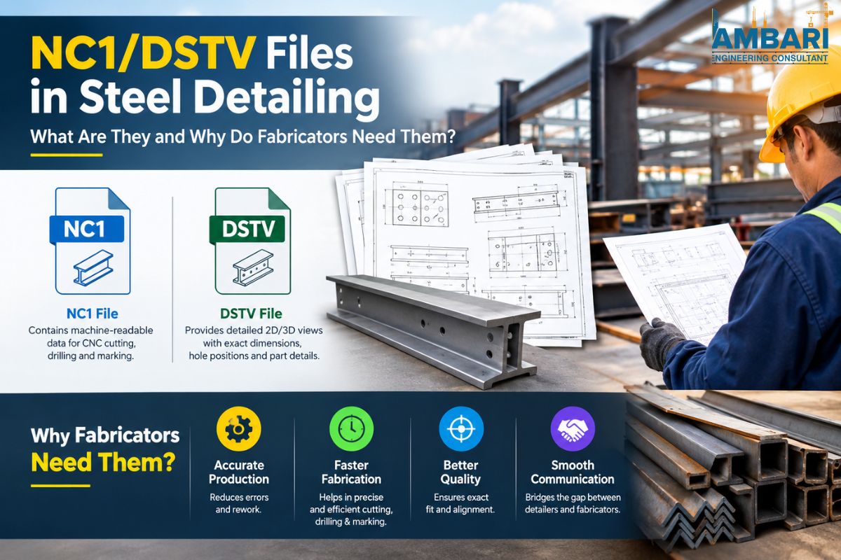
NC1/DSTV Files in Steel Detailing: What Are They and Why Do Fabricators Need Them?
NC1 and DSTV files are text files showing holes, cuts, bevels, and marks of one steel workpiece, for example, a beam or column. With their help, CNC machines produce the elements from the detailing model, and the shop does not have to measure and enter each dimension manually.
Key Takeaways
- DSTV is the industry norm. NC1 files denote members such as Beams, Columns, etc.
- One NC1 file per part will include all holes, cuts, bevels, and marks for that part.
- Most error detection in NC1 proceeds upstream from details by numbering, geometry, and exports.
- Preview files before export; you'll save much more time than correcting cut parts.
What are NC1 and DSTV files?
DSTV is a data standard published by the German steel construction association "Deutscher Stahlbau-Verband". The format provides a standard way to describe a steel component, enabling steel detailing and steel fabrication systems to share information without re-keying data.
NC1 is a file type founded on the DSTV technology. The 'NC' is a standard for numerical control in which computers direct the machines of the fabrication, while the '1' refers primarily to profile members—I-beams, channels, angles, and hollow sections. Related file formats are used for plate parts.
Therefore, the NC1 Files are plain text files and can therefore be opened with a simple text editor. Note: do not edit files by hand. The files should be edited in the detailing model and exported again. Steel fabrication drawings services in USA can be helpful.
How do NC1 and DSTV differ?
People often use the two terms as if they were the same thing. The relationship is simpler than it seems: DSTV is the rulebook, and NC1 is one of the files written under it.
| Term | What it refers to | Where you encounter it |
|---|---|---|
| DSTV | The standard that defines how steel part data is described | In export settings, machine specifications, and supplier requirements |
| NC1 | A file type under the DSTV standard, used mainly for profile members | As the actual file transferred to a beam line or CNC machine |
| NC (plate variants) | Related file types under the same standard, used for plate parts | When plates are cut on flame, plasma, or laser tables |
If a shop asks for "DSTV files," it usually means the full set of files its machines can read. If it asks for "NC1 files for shop fabrication drawing services in USA," it is usually referring to the beams, columns, and other profiles.
What information does an NC1 file contain?
An NC1 file is a series of instructions in an organized list for one part. One type of information is stored in each section of the file, known as a block. The first line of the file is a header that says what part the machine is to make, followed by a list of operations that the machine must perform.
How is the member described?
The header contains the basic identity of the part, type of profile, size of profile, steel grade if available, overall length, part mark, quantity, and the unit system used. The machine takes this data to verify that it has the correct profile and to prepare the material for the subsequent operation before the machine begins any operation.
What do holes, cuts, notches, and bevels look like in the file?
Every operation is characterized by position and geometry – both in relation to a known reference position on the member. Typical operations include:
- Holes: Position along the length, position across the web or flange, diameter, and depth if the hole is not through.
- Cuts and contours: The outline of a cope, notch, or end cut, given as a series of points.
- Notches and copes: Cut off corners or flanges at the ends of members; generally specified in terms of dimensions from a reference point.
- Bevels: Angles and the amount of angle that cuts the edge of the member to prepare for welding.
However, the machine performs these instructions one after the other. The file contains no picture of the part, so the level of accuracy of each number is critical.
Why does marking information matter?
A mark is a data mark used to mark the part, typically using scribing or stamping with a mark, number, or text string. This is how erectors and fitters are able to identify the right member on site. Even if the beam is properly made, it can end up where it does not belong if proper marking is not done.
How are NC1/DSTV files generated from a detailing model?
The file is a product of a computer, not handwritten. The process is done in the following general order:
- The detailer creates the model using members, connections, bolts, welds, and cuts, which are all attached to a fixed coordinate system.
- The export settings are set by the detailer. These include the unit system, reference point or side per member, names of profiles and those that are in the machine library of the shop, and which operations are to be included.
- In the export step, one file is generated for each part, with the model data in the standard's block structure.
- The files are inspected and then moved to the fabrication shop directly to the machine's controller or via the shop's production system.
Moreover, all of these settings can modify the output. In cases of a wrong reference side, for instance, all the holes on a member will be duplicated in the model without any notice.
How do fabricators use these files on CNC equipment?
Most shops use a beam line that is a CNC machine designed to drill, saw, cope, and mark profile members, with an NC1 file. Generally, parts are cut out using a flame, plasma, or laser cutting table, but parts are punched or drilled from some plates on special machines.
Therefore, the operator loads the file, while the controller sequentially reads each block. The machine then moves the member to its position, executes each operation, and marks the part. Other stores also utilize the profile to make sure that the profile loaded is the one described in the header prior to cutting.
A machine operates solely in accordance with the instructions in a file. If a hole is found 20mm away from the incorrect reference point, the machine will drill it 20mm from the incorrect point. That's why fabricators appreciate the accuracy of the files and why many shops perform a preview or simulation of the file before cutting the first piece.
What does the workflow look like from detailing to fabrication?
The typical NC1/DSTV workflow involves four steps:
- Detailing: The model is created and checked for collisions, proper member sizing, and access for bolt holes. Part numbers are assigned.
- Checking: The detailer verifies that the model is finished and all the numbers are unique before it is exported. Drawings are checked against the model, and open revisions are closed.
- Export: The files are created according to the proper settings. The output is retained, and a clear record of the revision from which it came is recorded.
- CNC fabrication: The shop loads the files, checks the profile and part data, spins the parts, and does final quality control on the finished parts before sending them to a painting or assembly stage.
All stages are dependent on the preceding one. If a mistake passes the check, it appears on the machine, and if a mistake gets to the machine, it will be much more costly to remedy the mistake. Coordinating with steel Connection Detailing Services in USA will be the smart choice.
What are the benefits for fabricators?
Fabricators who can make use of correct NC1/DSTV data tend to obtain the following benefits:
- Automation: machines run directly from the data; fewer operations are reliant on manual setup.
- Accuracy: Holes and cuts do not correspond to a hand-measured design, but are made according to the geometry of the model.
- Less manual data entry: dimensions are not required to be manually entered from drawings, thus eliminating a common source of error.
- Quicker production: machines can produce several parts with little change to the set-up, and repeat members have reduced programming time.
- Less fabrication error: There are fewer holes that are misdrilled and cuts of incorrect length when the data is clean and verified.
- Better coordination: detailing, fabrication, and erection work on the same set of drawings, eliminating disagreement over what was meant.
Furthermore, the quality of the files is the determining factor for these benefits. Bad data won't be corrected by automation. It repeats it more quickly.
What problems occur, and how can detailers prevent them?
Most NC1 problems fall into a small number of groups. The table below lists common ones along with preventive steps that detailers can take before export.
| Problem | Typical cause | Prevention before export |
|---|---|---|
| Holes in the wrong position | Reference point or side set incorrectly in export | Confirm the reference point and side for each member type |
| Part rejected by the machine | Profile name does not match the shop's library | Agree on profile naming with the fabricator at project start |
| Duplicate or missing part numbers | Copied members or numbering not reset | Run a numbering check and confirm every mark is unique |
| Wrong length or cut | Model edits not carried through to the file | Compare file length and key dimensions against the model |
| Marks missing or unreadable | Marking settings not included in export | Confirm marking blocks and text size with the shop |
| Files do not match current drawings | Export made before the final revision | Lock the revision and re-export after every change |
Why do model accuracy and numbering matter before export?
The NC file is only as reliable as the model behind it. A small error in a connection, a bolt pattern, or a member length does not stay small once it reaches the machine. It becomes a hole in the wrong place, a part that does not fit on site, or a delay while the shop waits for a replacement.
Numbering matters for a similar reason. Each part mark ties the file, the drawing, the bundle, and the erection plan together. If two members share a mark, the shop may cut the wrong piece, and the error may not be caught until the steel arrives on site.
However, machine requirements also shape the output. The fabricator's equipment has limits on profile sizes, cut types, and the number of operations per member. A detailer who knows those limits can avoid exporting details the shop cannot run, and can agree on alternatives early instead of during fabrication.
How should NC files be checked before fabrication?
Good checking is a repeatable process, not a one-time glance. Consider these steps:
- Confirm the revision number of the model, drawings, and files match.
- Check that every part has a unique mark and that the quantities match the bill of materials.
- Compare the length, profile, and grade in each file with the model.
- Spot-check several holes and cuts against their dimensions on the drawings.
- Confirm the reference side and coordinate origin for each member type.
- Verify that the profile names match the shop's machine library.
- Check that the marking data is present and readable.
- Review a preview or simulation of the cut sequence where the shop allows it.
- Record what was checked and by whom, so the export has a clear audit trail.
However, checking should be done by someone other than the person who built the model, where possible. A fresh set of eyes catches errors that the original author has stopped seeing.
A practical example: one beam from model to machine
Let’s take a wide-flange beam having a width of 6000mm that has an end plate and bolt holes on it. The detailer assigns the mark B-104 to the beam and checks for clashes and correctness of numbering in the model. The NC1 file is sent using all the proper files, reference points, and marking details.
Before it can be sent to the fabrication shop, the detailer again verifies the file length, bolt hole distance, and marks with the drawing provided. The shop attendant loads the file into the beam machine, which drills holes through the beam, cuts the scope, and marks it as well. The fitter then utilizes the mark to place the beam properly while working on assembly as well as erection.
Conclusion
NC1 and DSTV files link the detailing model to the steel manufacturing machines. These precise files ensure the manufacturing process runs smoothly while also preventing shop floor errors. Numbering correctly, modelling with precision, exporting with the right settings, and checking files can prevent costly errors. Better files for better fabrication.
Ambari Consultant provides structural steel detailing services USA, including steel fabrication drawings, shop fabrication drawing services, and steel connection detailing services, with fabrication needs considered from the beginning.
Frequently Asked Questions
1. What is an NC1 file used for?
An NC1 file gives a CNC machine the instructions to fabricate one profile member, such as a beam or column. It lists the holes, cuts, notches, bevels, and marks in a structured text format.
2. Is DSTV the same as NC1?
No. DSTV is the standard that describes how the data for a steel part should be described. NC1 is one of the file types within that standard and is primarily for profile members.
3. Can any detailing model produce NC1 files?
Many modern detailing programs have the capability of exporting DSTV-compatible files; however, your export settings and the shop's machine requirements need to match. Confirm the format and settings with the fabricator before the project starts.
4. Do fabricators still need drawings if they have NC1 files?
Yes. Drawings show all the assembly, connection, and erection details that a machine file doesn't have. The NC file drives the machine, and the drawing guides assembly and inspection.
5. Why does a machine sometimes reject an NC1 file?
The number one reason is that the profile name does not match the machine's library, a setting on the unit or reference that is different than the shop standard, or a file that has an operation that the machine cannot do.
6. Who creates NC1/DSTV files?
These files are created during export from the detailing model. The detailer builds the model and export options, and the fabricator verifies they match the equipment.
7. Can NC1 files be edited by hand?
Technically yes, because they are plain text. However, in practice, make changes in the model and regenerate the file, so the model, drawings, and machine data can all be kept in sync.
8. How can detailers reduce NC1 errors?
They can agree on settings and profile naming at the start of the project, check the model and numbering before export, lock revisions, and review key dimensions in the file. A repeatable checklist catches most common mistakes.